Yousef Alhorr1, Qusai Alkhalaf 2*
1PhD, Chairman of Gulf Organization for Research and Development (GORD), QSTP, Doha, Qatar
2PhD, Additive manufacturing center operations lead. Gulf Organization for Research and Development (GORD-3D), QSTP, Doha, Qatar
Abstract: The manufacturing of closed impellers via Laser Powder Bed Fusion technology entails inherent complexities, demanding meticulous attention to support structure design, determination of building angle, and down-skin energy density to ensure successful production. This study explores the use of stainless steel 316L in fabricating closed impellers using LPBF. The aim is to investigate the impact of process parameters and building angles on impeller fabrication quality. In addition to studying the effect of energy density on the surface roughness and hardness values of the impeller. The investigation examines building angles of 0˚, 30˚, and 90˚ for a closed impeller, revealing that a 30˚ building angle yields successful printed parts. Moreover, to achieve defect-free closed impellers, it is imperative to maintain down-skin energy density between 80% and 100% of in-skin energy density. The maximum hardness and minimum surface roughness were recorded at 233 HV and 12.79 µm, respectively, when the energy density was 41.66 J/mm³ and 55.55 J/mm³ respectively. The novelty of this study lies in the fabrication of closed impellers using stainless steel 316L through laser powder bed fusion.
Keywords: additive manufacturing; laser powder bed fusion (LPBF); closed impeller; selective laser melting (SLM)
1. Introduction
The impeller constitutes an indispensable element in pump systems, playing a pivotal role in dictating hydraulic capacity and flow rate efficiency within turbomachinery [1]. Distinguished by four geometric classes namely, open, closed, semi-open, and screw impellers, the closed impeller (CI) stands out as particularly challenging to manufacture due to intricate internal features. Traditional methods involve assembling CI in segments, such as shroud, hub, and blades, employing joining techniques like welding, brazing, or riveting. However, these approaches introduce defects and distortions, proving inadequate for demanding, high- performance applications. Consequently, the adoption of single-piece CI becomes imperative, with manufacturing techniques like investment casting, integral milling, and electron discharge machining (EDM) being specialized but time-consuming, requiring skilled labor and specialized setups, consequently elevating overall manufacturing costs [2].
Addressing these challenges, Additive Manufacturing (AM) emerges as a transformative solution for single- piece CI, offering the prospect of mitigating lead time uncertainties and enhancing design flexibility [3,4]. Laser Powder Bed Fusion (LPBF), a prominent AM technology, selectively melts powder layer by layer using a laser, thereby enabling the production of intricately shaped parts with a high resolution of approximately 50 micrometers [6-9]. LPBF has demonstrated considerable success in printing complex parts from an array of metallic materials, including steels, nickel alloys, titanium alloys, and Inconel alloys [10-11].
While alternative technologies such as Fused Deposition Method (FDM) can be utilized for impeller printing, their suitability is generally confined to less intricate applications [12]. In contrast, LPBF with metal printing is indispensable for achieving high-performance functionalities [13]. Numerous studies underscore the successful application of LPBF in printing open impellers, encompassing investigations into material properties, thermal history predictions, and optimization of process parameters [14-16]. Significantly, LPBF allows for the fabrication of impellers from recycled materials, accentuating its potential for sustainable manufacturing practices [17]. Despite these advancements, persistent challenges revolve around achieving precise and defect-free 3D prints. Geometric deformation, exemplified by dark spots and suboptimal metallurgical bonding between layers, contributes to multifaceted issues, including geometric failure, dimensional inaccuracies, incomplete structures, and impediments in the printing process [27]. Moreover, debris defects, arising from the recoil pressure of metal vapor during printing, result in unfused powder or molten metal breaking away and influencing the melting status in successive layers, ultimately compromising the tensile strength and fatigue performance of the printed part [28- 29]. Table 1 shows the summary of impeller process parameters with different materials.
Table 1. Summary of Impeller Process Parameters
| References | Material | Type of impeller | scan speed(mm/s) | Power (W) | Layer thickness(µm) | Spot diameter of the laser(µm) | Hatchspacing(µm) |
| Mikula et al [14] | Inconel 718 | Closed impeller | 960 | 258 | 40 | - | 110 |
| Tupac et al.[17] | Inconel 718 | Closed impeller | 1000 | 150 | 30 | - | 70 |
| Kladovasilaki s et al. [18] | Stainless steel 17-4PH | Open impeller | 1200 | 107 | 25 | 50 | 30 |
| Tian et al. [19] | Ti-6Al-4V alloy | Closed impeller | 250 | 800 | - | - | - |
| Guo et al. [20] | TC4 | Closed impeller | 1000 | 150 | 30 | - | 140 |
Stainless steel is widely regarded as an excellent option for laser powder bed fusion printing. A stainless- steel closed impeller has numerous applications, such as in wastewater systems. Key concerns when printing stainless steel involve managing energy density and optimizing the support material angle. This metric encapsulates the energy input per unit volume during the layer melting process. Specifically, the energy density is defined as:

In the equation, P (W) represents laser power, v denotes scanning speed (mm/s), h (μm) denotes hatch distance, z (μm) indicates layer thickness, Low-energy levels lead to lack-of-fusion porosity, indicating insufficient energy for complete powder melting and resulting in widespread irregular porosities throughout the part [31]. High-energy density values cause over-melting, often termed as keyhole porosity [32-34]. In this state, molten tracks fragment, causing non-uniform solidification and final part defects. The steady region ensures complete track melting and layer bonding within energy density limits. Impeller printing complexity is key in laser powder bed fusion, with common metals being Inconel 625 and Inconel 718.
To the best of the authors' knowledge, there exists a notable absence of investigations regarding the application of Stainless Steel 316Lin the laser powder bed fusion printing of closed impellers. Hence, this research is poised to fill this void by undertaking the production of a closed impeller via laser powder bed fusion. Our main objective is to analyze the impact of variables such as support material, angle of construction, and down-skin energy density on the fabrication process of the closed impeller. Additionally, we aim to investigate the effect of energy density on surface roughness and hardness.
2. Method and Experiment Work
The method and experimental work applied here to study the angle of the support structure and the final mechanical properties of the impeller are illustrated in Figure 1. The method is divided into three phases. The first phase involves selecting the appropriate support structure angle between 0°, 30°, and 90°. Once the optimized angle is determined, it is examined for microstructure texture using SEM scanning for phase 2. Phase III focuses on examining the effect of energy density on roughness and hardness.
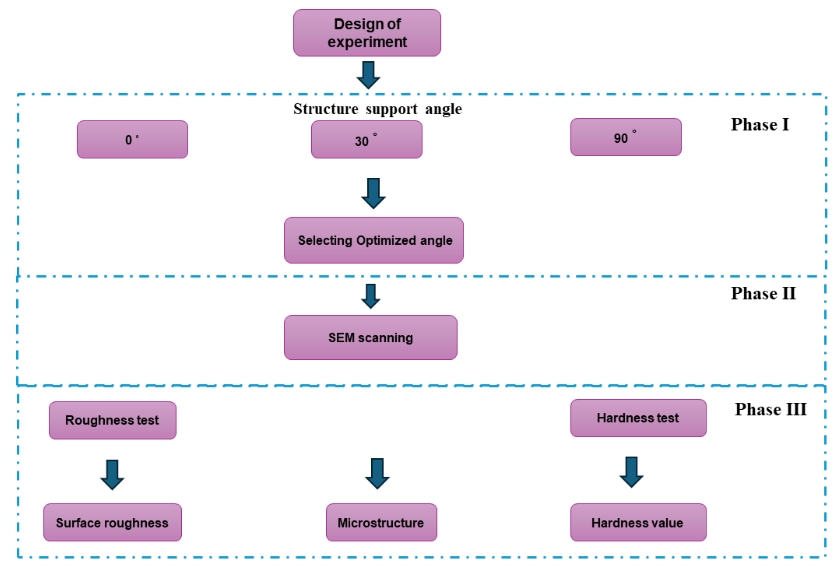
Figure 1. Design of experiment structure
2.1 Design of Impeller
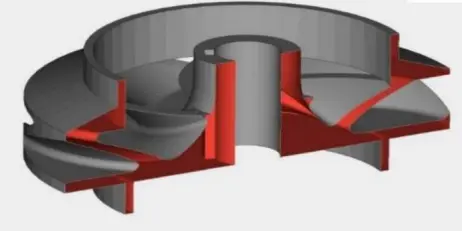
Two different sizes of enclosed impellers were designed: one with a diameter of 145 mm and the other with a diameter of 100 mm. The impeller is divided into three main sections along its construction direction: the base, midsection, and fin section. These sections have complex structures, including several inclined thin fin geometries, which makes manufacturing a challenging process. Because the cross-section changes along the height of the impeller, the area scanned by the laser varies from layer to layer. The structure of the impeller is shown in Figure 2.

Figure 2. Design of Impeller Structure
2.2 Building Angle and Support Structure for Closed Impellers
To determine the optimal building angle for a closed impeller within the LPBF machine's build chamber, three common angles (90˚, 30˚, and 0˚) were selected to assess their impact on the manufacturing process. The selection of supports depends on the impeller's shape, with block-shaped supports chosen, as depicted in Figure 3. Numerous studies have shown that employing solid or block supports leads to improved mechanical characteristics in samples and superior surface finishing, especially for overhanging surfaces. These supports facilitate effective heat dissipation, thereby optimizing outcomes. Figure 4 illustrates the view of block support, with tree supports added to facilitate easier removal. The software used for build preparation was MaterialsMagic for preparing the supports, and SolidWorks was utilized for design purposes.
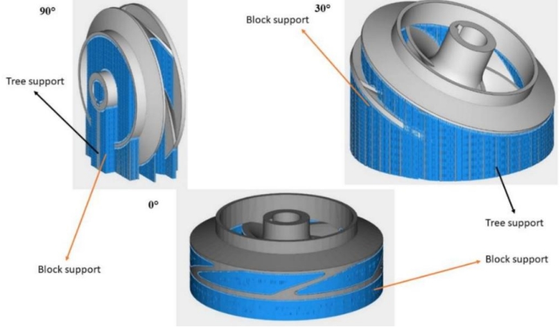
Figure 3. Types of support structure for closed impellers

Figure 4. View of support structure of closed impeller
2.3 LPBF processing
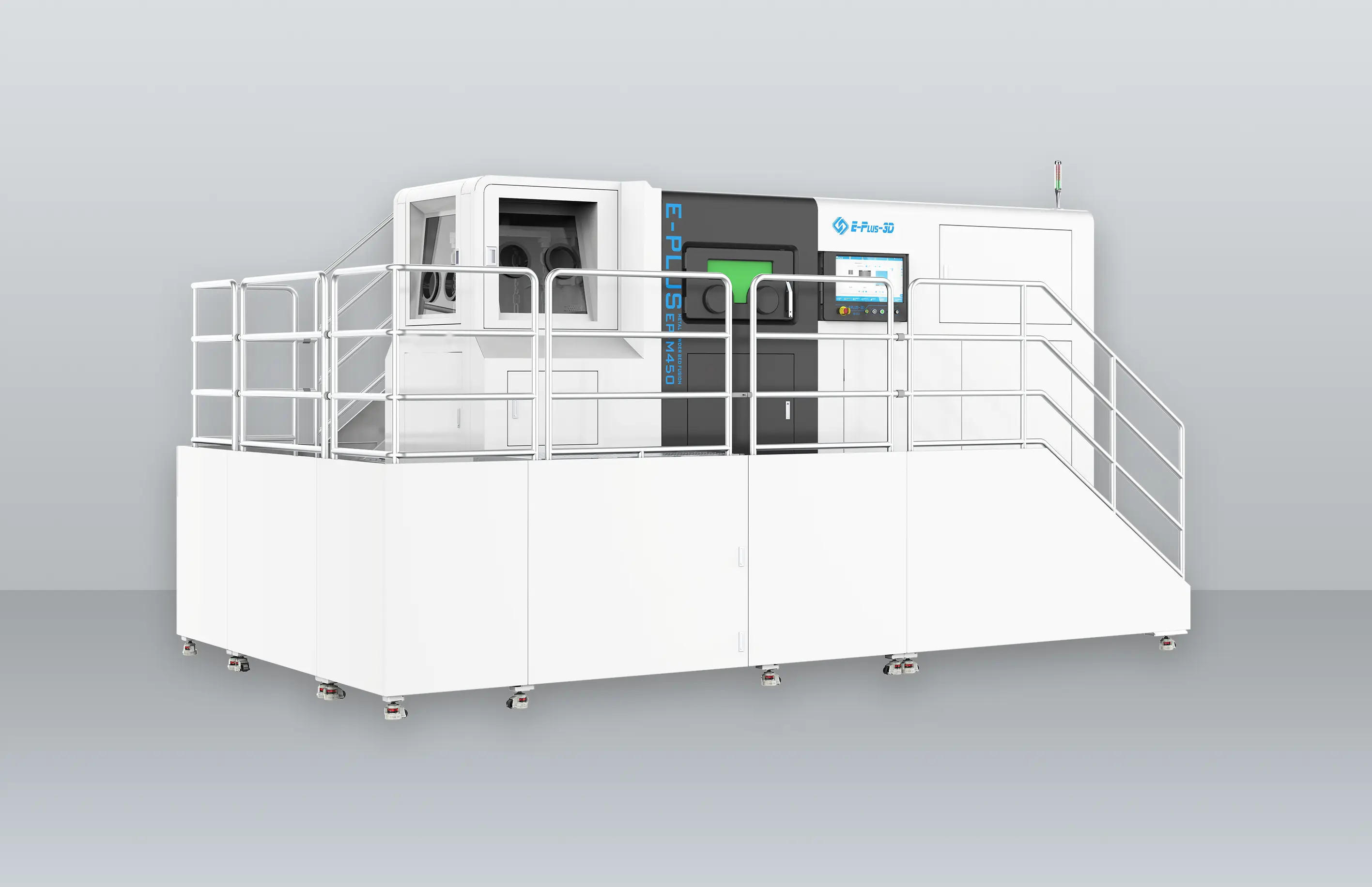
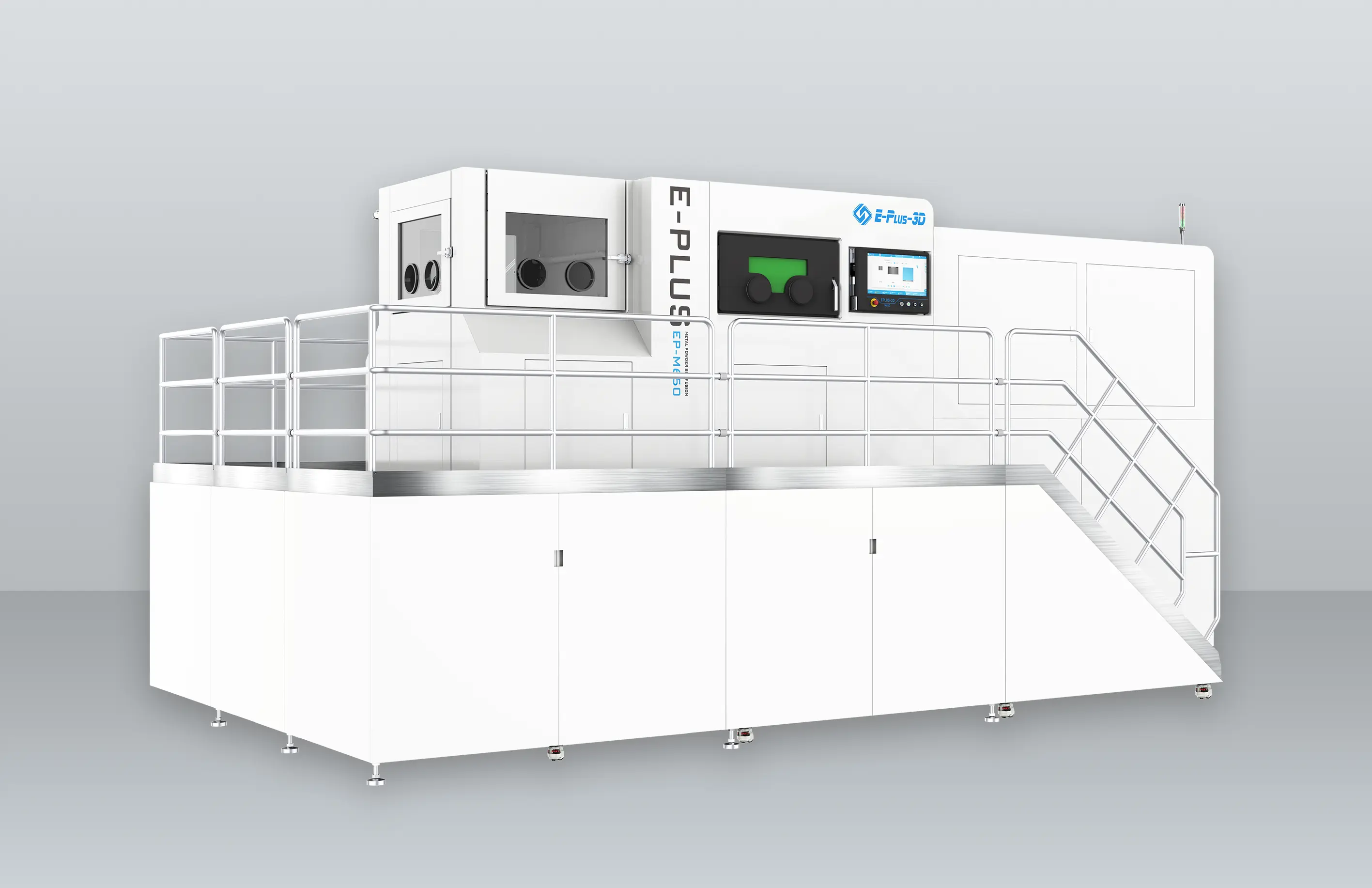
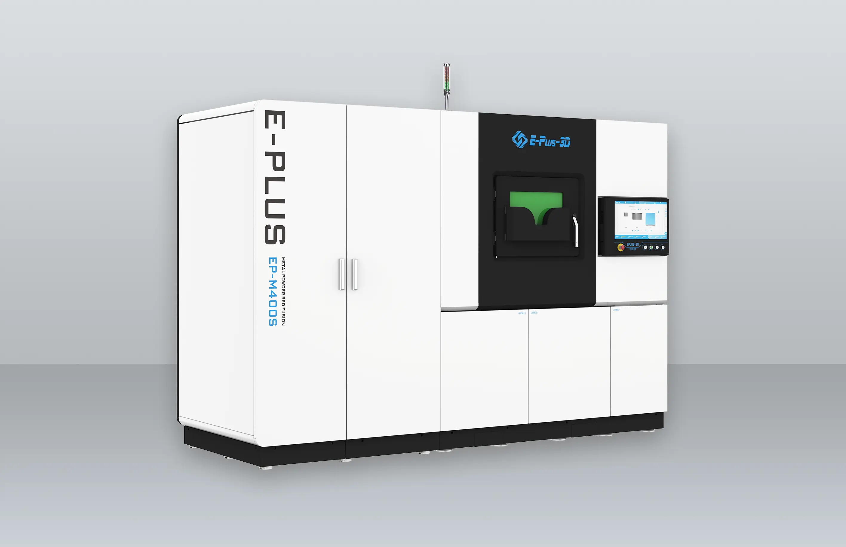
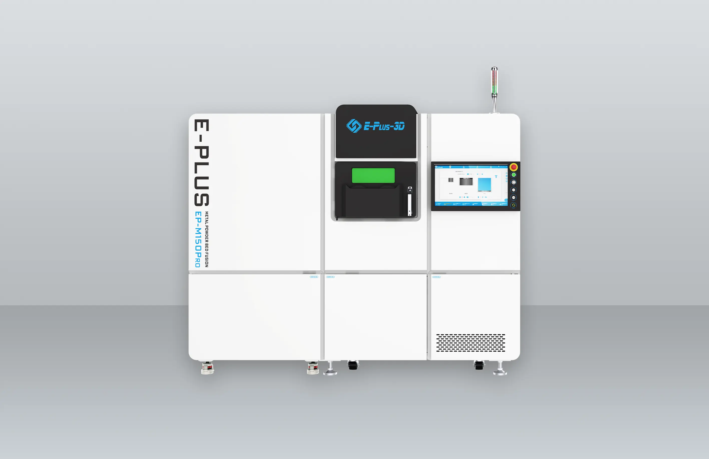
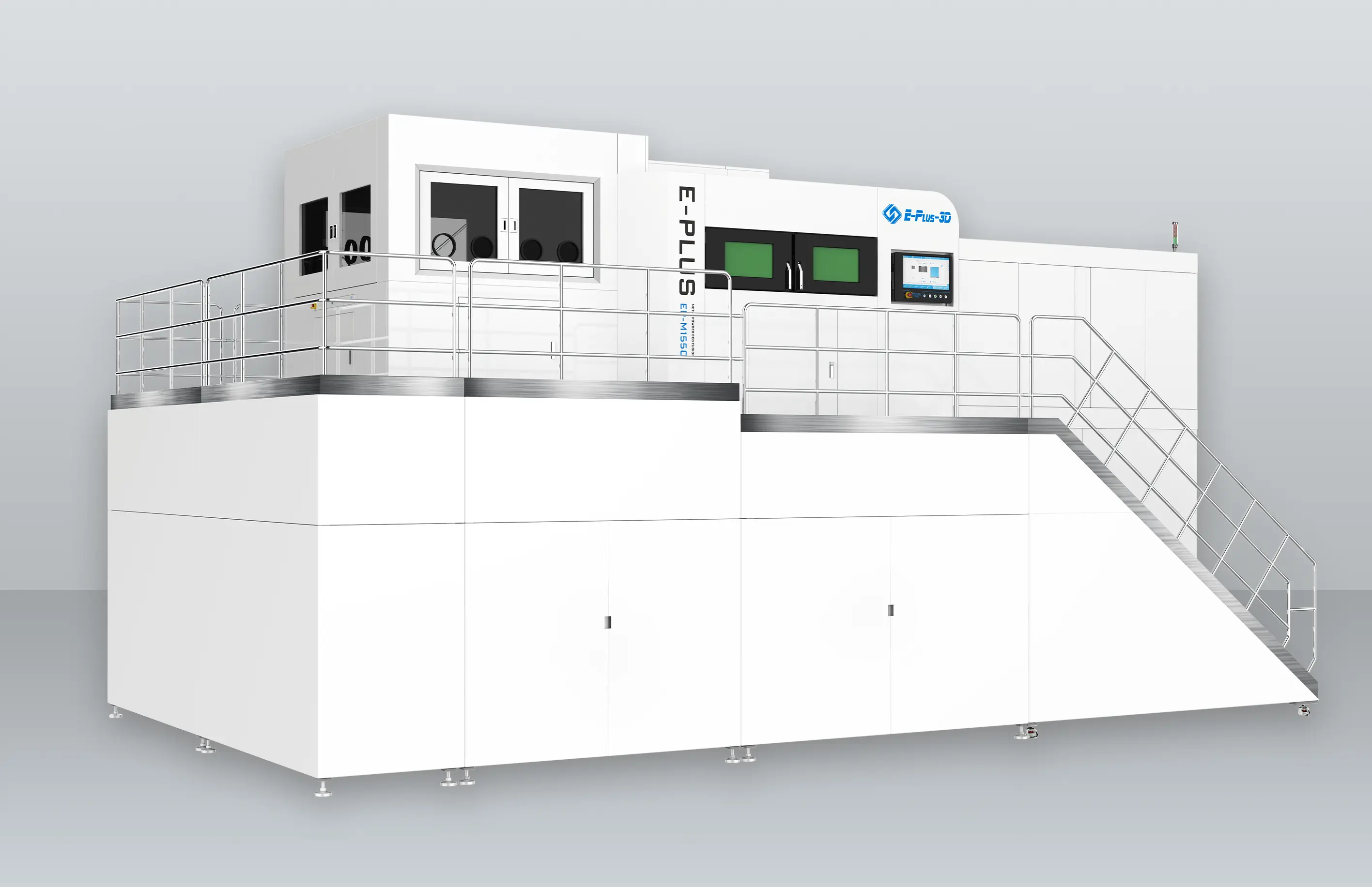
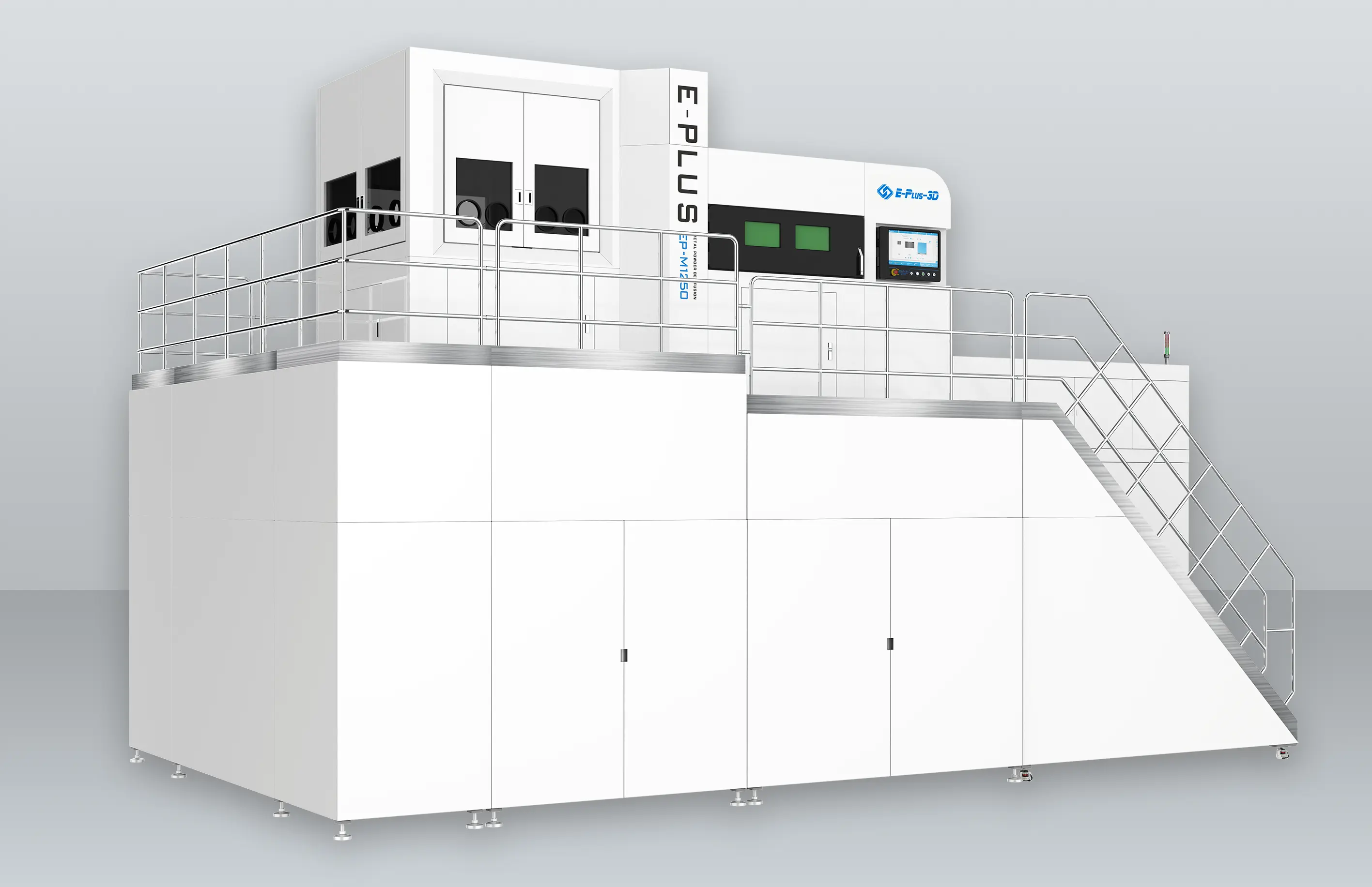
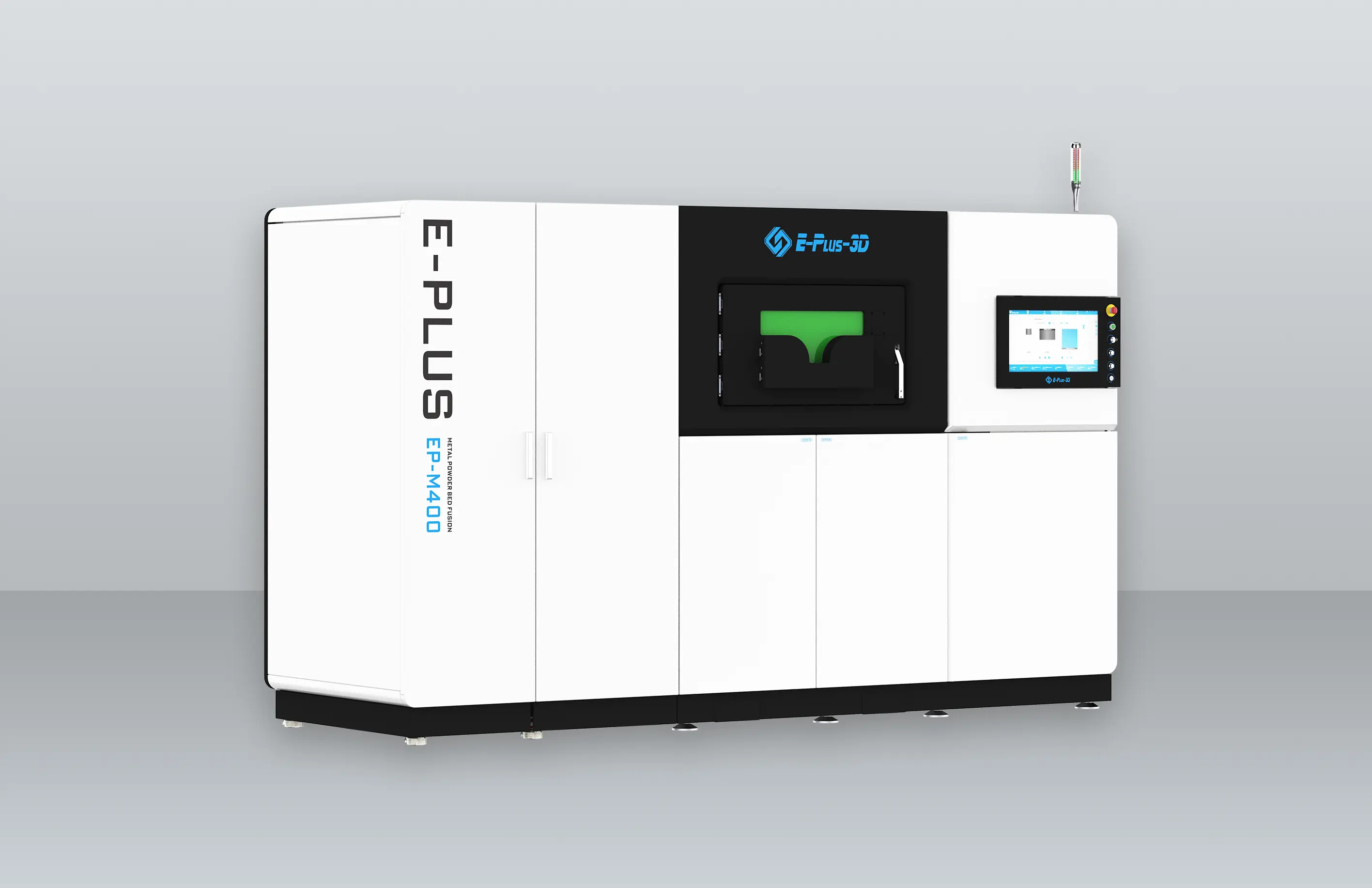
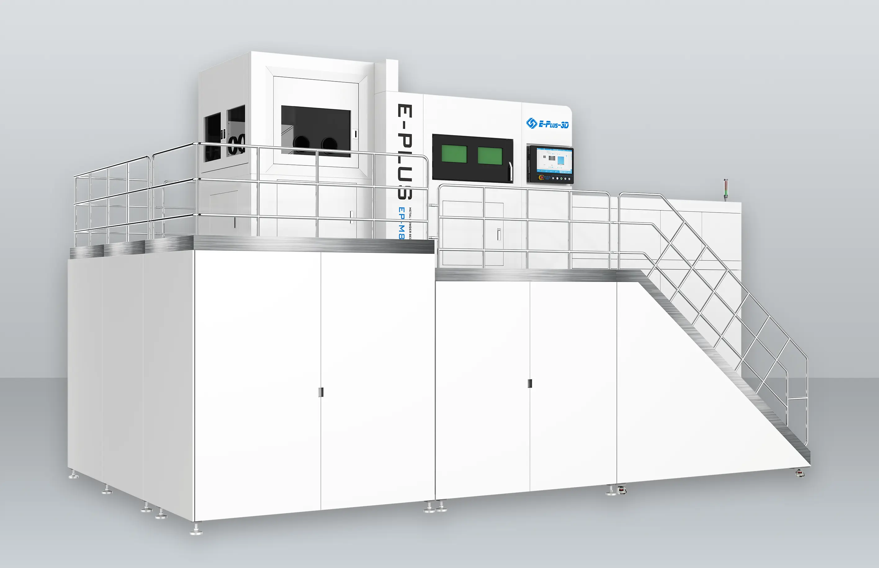
The impellers were manufactured using an Eplus3D EP-M260 LPBF Machine, employing stainless steel 316L material. The Eplus3D M260 is situated at the Gulf Organisation for Research & Development's 3D Centre (GORD 3D). The actual view of the Eplus3D machine is shown in Figure 5. The impellers were designed with diameters of 145 mm and 100 mm. Printing a 145 mm diameter impeller at a 90˚ building angle takes approximately 103 hours, requiring 4,393 layers with a thickness of 30 µm. A 145 mm diameter impeller printed at a 30˚ building angle requires 53 hours, spanning 3,124 layers. A 100 mm diameter impeller printed at a 0˚ building angle take about 38 hours, with 1,833 layers.
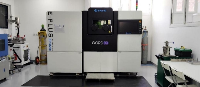
Figure 5. Eplus3D EP-M260 Laser Powder Bed Fusion Machine
Selecting parameters for printing closed impellers is crucial, with the energy density being a particularly important consideration. The down-skin is located within the first three layers above the support material, which can potentially damage the part during the printing process. Therefore, selecting the down-skin energy density perfectly is essential, as it serves as a bridge between the support material and the core of the impeller. The in- skin energy density, on the other hand, pertains to the core of the impeller. According to the literature review, the down-skin energy density should ideally range from 50% to 80% of the in-skin energy density. In the present study, two cases are considered for the down-skin density: one where the energy density of down-skin is equal to that of in-skin energy density, and another where the energy density of down-skin is set to 20% of the in-skin energy density. The current view of the printing process is depicted in Figure 6. Tables 2 provides details of the process parameters with these energy density variations for each phase.
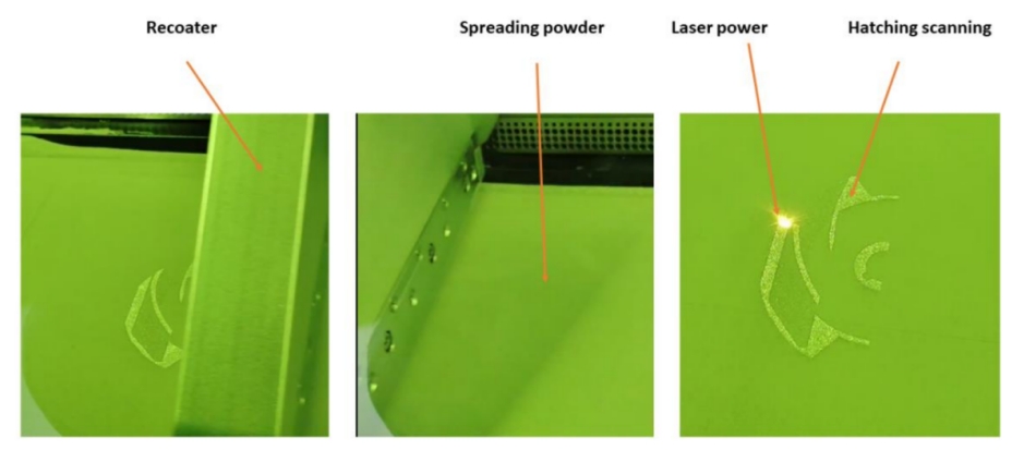
Figure 6. Process manufacturing of a closed impeller
Table 2. Process parameters of laser powder bed fusion
| Sn. | Diameter of impeller (mm) | Building degree (˚) | In-skin speed mm/s | In-skin power W | In-skin energy density(J/mm3) | Down-skin speed mm/s | Down-skin power W | Down-skin energy density(J/mm3) |
| Phase I |
| CI- A | 145 | 90 | 900 | 240 | 55.55 | 2400 | 140 | 12.15 |
| CI-B | 100 | 30 | 900 | 240 | 55.55 | 2400 | 140 | 12.15 |
| CI-C | 145 | 0 | 900 | 240 | 55.55 | 2400 | 140 | 12.15 |
| CI- D | 100 | 0 | 900 | 240 | 55.55 | 2400 | 140 | 12.15 |
| CI-E | 100 | 0 | 900 | 240 | 55.55 | 2400 | 140 | 12.15 |
| Phase II |
CI- C-I-1 | 145 | 30 | 900 | 240 | 55.55 | 2400 | 140 | 12.15 |
CI- C-I-2 | 145 | 30 | 1300 | 220 | 35.25 | 1300 | 220 | 35.25 |
| Phase III |
| CI- C-1 | 145 | 30 | 1000 | 60 | 33.33 | 1000 | 60 | 33.33 |
| CI- C-2 | 145 | 30 | 900 | 60 | 37.037 | 900 | 60 | 37.037 |
| CI- C-3 | 145 | 30 | 800 | 60 | 41.66 | 800 | 60 | 41.66 |
| CI- C-4 | 145 | 30 | 600 | 60 | 55.55 | 600 | 60 | 55.55 |
2.4 Hardness test
Vickers micro-hardness tests were performed following ASTM standard E92-17 using a Vickers micro- hardness testing machine. A pyramidal diamond tip indenter applied a specified force (300 gf, 2.94 N) to the sample surface for 10 seconds per indentation. Three indentations were made on each sample, with any indents within pores excluded. The Vickers hardness value (HV) was determined by measuring the diagonals of each diamond-shaped indent, averaged using the machine's software. the average of these measurements considered the sample's hardness.
2.5 Surface preparation and microstructural characterization
A 5-mm-thick sample was produced with the impeller. The samples underwent abrasion using silicon carbide abrasive discs of various coarseness levels (200, 600, 800, and 1200 grit). These processed samples were then examined under an optical microscope to study microstructural features including, unmelted powder and flaws. Subsequently, they were analyzed using a Phenom ProX Desktop SEM to investigate substructure and morphology.
3. Result and Discussion
3.1 Influence of Building Angle on Impeller Building
Support structures play a vital role in dissipating heat from the melt pool, reducing thermal stresses, and counterbalancing recoating blade force, which exerts dynamic pressure against the layer's leading edge. Heat conduction varies based on relative density; it is significantly lower in powder layers with lower packing densities than in solid-supported structure. Different support structures dissipate heat at various levels; however, more heat dissipation,such as with block supports, makes removal more challenging. Solid/block supports facilitate superior mechanical properties and surface finishing on overhanging surfaces, albeit at increased material, printing time, and post-processing costs. Besides heat dissipation, support structures sustain parts and counteract tensile forces during rapid cooling, mitigating warping and delamination risks. Insufficient support for downward-facing surfaces leads to shape and dimensional accuracy issues. Hence, selecting parameters for support and down-skin layers is crucial to mitigate internal stresses and delamination. It is crucial to ascertain a "reliable building angle," denoting the minimal angle ensuring part production without dross formation and detachments.
As described in the methods section, the impeller was examined at three building angles during construction: 90°, 30°, and 0°. In the case of CI-A, a significant impeller failure occurred, attributed to weak support structures chosen prior to the process, as shown in Figure 7. The combination of block support and tree support proved inadequate to support the weight of the impeller, leading to deformation of the support structure, particularly noticeable at a 90˚ building angle. The observed deformation can be attributed to the significant weight exerted by the built part and the recoater during the printing process. The recoater, in particular, plays a critical role in the layering process by spreading the powder across the build bed. However, this repetitive action, especially during the application of subsequent layers, can exert excessive force, leading to damage, particularly at 90°angles where the edges of the printed part are inherently weaker.
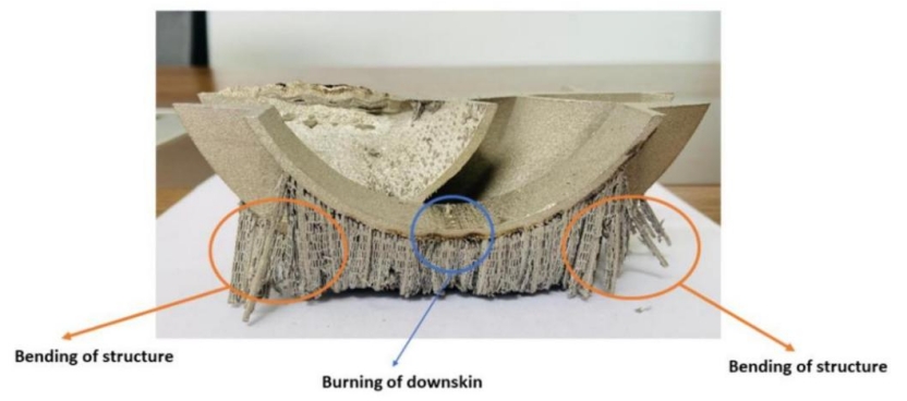
Figure 7. Damage of the support structure during the process (CI-A)
In the cases of CI-B and CI-C, successful impeller construction with fewer defects was observed. The production of a smaller and big impeller with a building angle of 30˚ notably reduces defects and damage during the manufacturing process, exhibiting superior outcomes compared to instances where the building angle is set at 90˚ . This phenomenon is clearly shown in Figure 8. No damages occurred due to the 30˚ building angle, which reduced the weight of the printed part and enhanced the performance of the recoater. At a 30°angle, the recoater comes into contact with less powder along the edges compared to angles of 90°and 0°during each spreading motion. The success of the 30-degree orientation is attributed to several key factors. Firstly, the gradual transition in cross-section from supports to solid parts within each layer minimized stress concentrations and potential defects, distinguishing it from orientations like 0 degrees where abrupt changes occur. Secondly, the absence of solid supports typically required for overhangs in orientations such as 90 degrees contributed significantly to the 30-degree orientation's success. This elimination of supports not only streamlined the printing process but also mitigated challenges associated with post-processing and surface imperfections, ultimately enhancing part quality and structural integrity. Additionally, it was observed that parts printed at a 30-degree orientation exhibited a reduced weight compared to those printed at 90 degrees. This weight reduction, while advantageous in various applications, further underscored the efficacy of the 30-degree orientation. Collectively, these findings highlight the multifaceted advantages of the 30-degree orientation in additive manufacturing, offering valuable insights for optimizing orientation strategies in future applications.
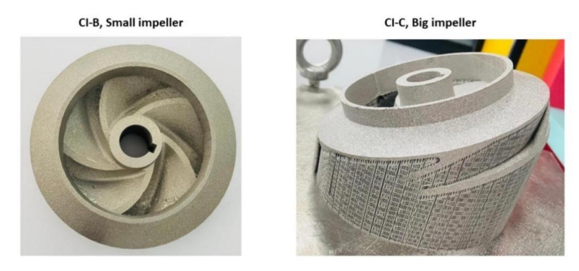
Figure 8. Successful impeller construction at 30˚ angle building
In the case of CI-D, when the closed impeller is small, failure occurred when the building angle was 0˚ . Despite the small size of the CI, failure at this angle was not due to its size, but rather attributed to the weakness in the support structure, as depicted in Figure 9. Additionally, the use of high scanning speed of 900 mm/s resulted in debris accumulation on the impeller surface, as illustrated in Figure 9. Furthermore, damage was observed along the border, caused by the high-power settings at these regions.
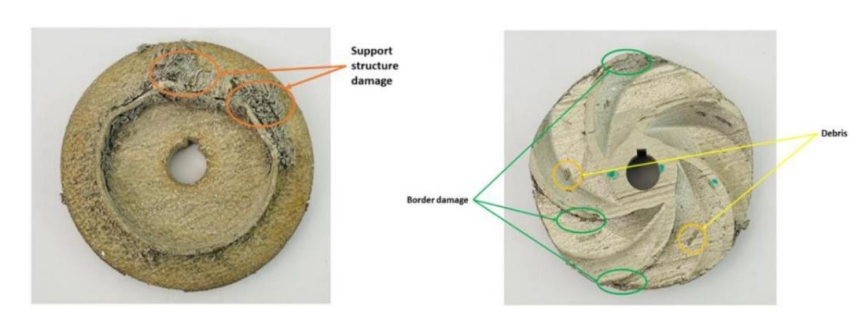
Figure 9. Support structure damage and debris for CI-D sample
3.2 Impact of Down-Skin Parameters on Closed Impeller Construction
Down-skin typically denotes layers, typically ranging from 1 to 4, positioned above supports or directly on the powder. Usually, three layers are identified as down-skin and necessitate distinct processing parameters compared to "in-skin" or "core" layers. Parameters related to down-skin, such as scanning speed and power, are deemed critical for constructing any part using laser powder bed fusion technology. When the down-skin energy density accounts for only 20% of the in-skin energy density, noticeable damage occurs on the part. Even in cases where no damage is observed, signs of burning and defects manifest on the surface of the closed impeller, particularly evident in larger closed impellers like CI-A, as depicted in Figure 7. This underscores the importance of two primary factors contributing to part failure: the inadequacy of the support structure and the insufficient energy density of the down-skin, which measures at 12.15 J/mm³.
As the impeller diameter decreases, as in the case of a 100 mm diameter impeller, the impact of the down- skin diminishes, especially notable at a building angle of 30˚ . Despite the down-skin energy density accounting for only 20% of the in-skin energy density, there may still be minor burning observed in specific areas of the printed part, as depicted in Figure 10. Furthermore, increasing the diameter of the impeller heightens the probability of part damage. However, aligning the down-skin energy density with the in-skin energy density at a 30˚ angle ensures successful impeller printing without defects, as it is shown in Figure 10.
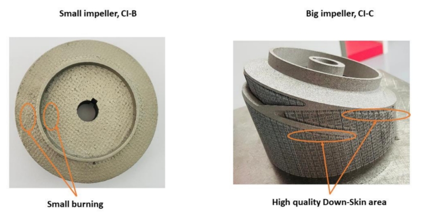
Figure 10. Impact of down-skin with big and small impeller with 30˚ angle
The down-skin energy density is a crucial parameter in the part-building process, determined by the complexity and size of the part. In smaller parts, its impact is less pronounced compared to larger ones. To achieve defect-free parts, the down-skin energy density should ideally range between 80 and 100% of the in-skin energy density.
3.3 Effect of volumetric energy density (VED) on microstructure of impeller
The printed impeller with an energy density of 35 J/mm³,considered low, exhibits a lack of fusion attributed to the high scanning speed, resulting in insufficient time for the laser to melt the powder, as depicted in Figure 11. By increasing the energy density to 55.55 J/mm³,these issues of lack of fusion and lack of adhesive are diminished due to the optimal energy density, allowing the powder to melt properly, as illustrated in Figure 12.
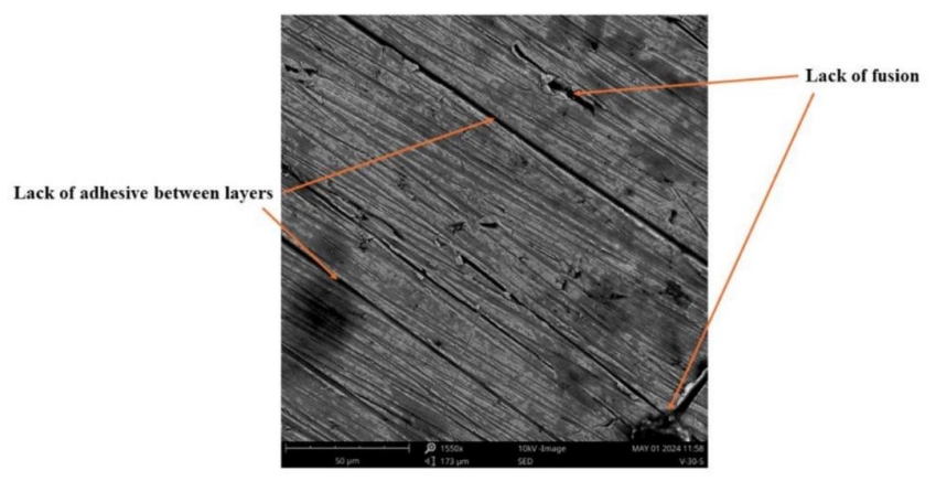
Figure 11. Micrographs showing samples with 35.25 J/mm3 for CI-C-I-1
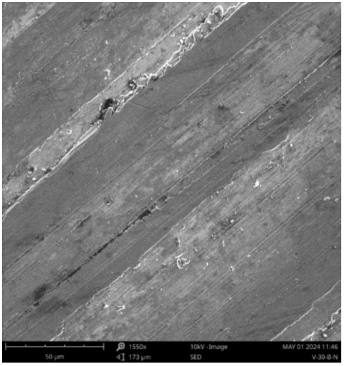
Figure 12. Micrographs showing samples with 55.55 J/mm3 for CI-C-I-2
3.4 Influence of VED on hardness
The Vickers hardness measurements of the printed samples ranged approximately from 226 to 233 HV. Two samples, characterized by a Volumetric Energy Density (VED) of 40 J/mm³,exhibited hardness values below 230 HV. Specifically, samples CI-C-1and CI-C-2, with energy densities of 33.33 J/mm³ and 37.037 J/mm³, respectively. The majority of samples fell within the range of 220 to 230 HV as it is shown in table 3. Notably, sample CI-C-3, possessing a VED of 41.66 J/mm³,exhibited the highest hardness of 233 HV.
The Vickers hardness (HV) values obtained were comparable to those of 316L parts manufactured by casting, which typically exhibit a hardness of 210 HV. However, the remaining values were higher than this benchmark. It's observed that the more porous a sample is, the lower its hardness, as the presence of pores allows indentations to penetrate more deeply, resulting in larger indents and consequently lower HV values. In this experiment, intentional efforts were made to avoid surface pores during each indentation, resulting in minimal correlation between hardness and surface porosity.
Table 3. Hardness measurements of samples phase III
Sample | Energy density(J/mm3) | Hardness (HV) |
CI-C-1 | 33.33 | 226 |
CI-C-2 | 37.037 | 225 |
CI-C-3 | 41.66666667 | 233 |
CI-C-4 | 55.55555556 | 231 |
3.5 Surface roughness
Surface roughness is an important parameter in laser powder bed fusion, influenced by the energy density. Increasing the energy density typically leads to a reduction in the average roughness of the part. This reduction occurs because higher energy density allows for more prolonged exposure to high energy and low speed, facilitating better powder melting during the process. Moreover, decreasing the scanning speed increases the energy density,consequently reducing the balling effect during processing, further contributing to reduced surface roughness. For instance, in Figure 13, the maximum surface roughness is observed at 13.82 µm when the energy density is low. However, increasing the energy density to 55 J/mm3 results in a decrease in surface roughness to 12.79 µm.

Figure 13. Average of surface roughness of impeller
3.6 Comparative with previous study
The results were compared with the literature review based on the hardness test, particularly comparing them to Eliasu et al[35]. Near mechanical properties, we observed small differences in the hardness test compared to Eliasu et al[35], with a range value change between 2 and 5 HV, as shown in Table 4. Upon comparison of the microstructure, it is noticeable that the microstructure of Eliasu et al. [35] is better than our present result, which may have caused the observed changes in hardness, as depicted in figure17.
Table 4. Comparison of hardness values with Eliasu et al. [35]
Energy density(J/mm3) Eliasu et al [35] | Energy density(J/mm3) ( Eliasu et al[35]) | Hardness (HV) (Present work) | Hardness (HV) Eliasu et al[35]) |
34.01 | 33.33 | 226 | 227 |
39.68 | 37.03703704 | 225 | 224 |
44.44 | 41.66666667 | 233 | 235 |
55.56 | 55.55555556 | 231 | 231 |
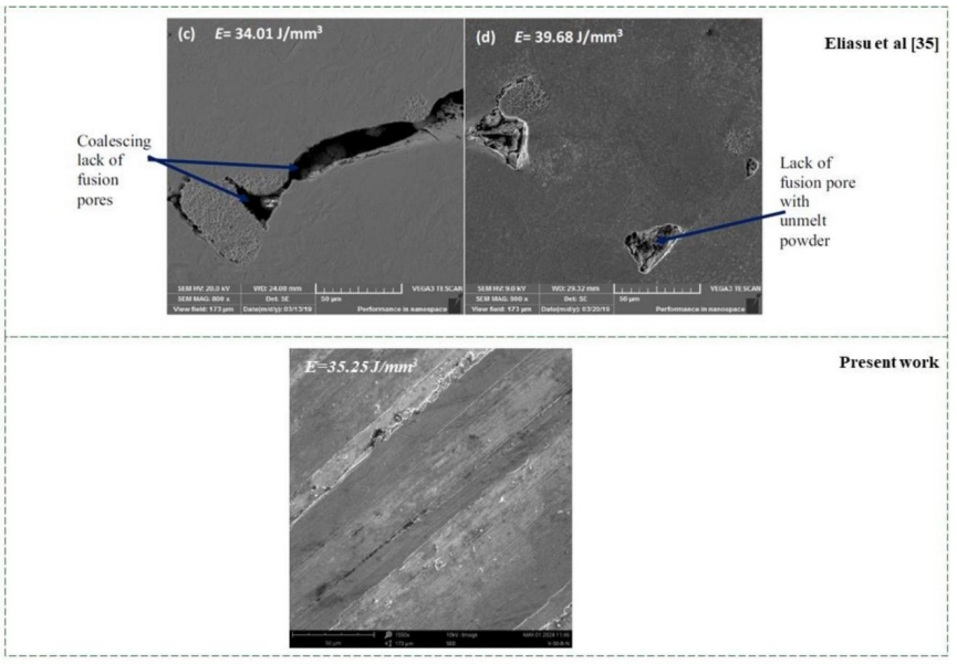
Figure 14. Comparative of microstructure of printed with Eliasu et al. [35]
4. Conclusions
Printing a closed impeller via laser powder bed fusion requires careful considerations for printing parameters to mitigate the complexities associated with the printing process. These include subtle design for proper selection for building angle, and use of adequate down-skin energy density for successful fabrication. In this study, stainless steel 316L is utilized for manufacturing the closed impeller through LPBF technology. To achieve successful printed parts and enhance the overall quality of closed impellers, optimal combination of several crucial factors must be ensured.
• The utilization of a smaller and big impeller with a building angle of 30˚ notably reduces defects and damage during the manufacturing process, exhibiting superior outcomes compared to instances where the building angle is set at 90˚ .
• Aligning the down-skin energy density with the in-skin energy density at a 30˚ angle ensures successful impeller printing without defects.
• When the down-skin energy density accounts for only 20% of the in-skin energy density, noticeable damage occurs on the part. Even in cases where no damage is observed, signs of burning and defects manifest on the surface of the closed impeller, particularly evident in larger closed impellers.
• Increasing the energy density to 55.55 J/mm3 leads to a reduction in unmelted powder during the process.
• Increasing the energy density decreases the surface roughness to 12.79 µm when the energy density is 55 J/mm3.
• The hardness of the impeller varies between 226 and 233 HV, reaching a maximum at 233 HV when the energy density is 41.66 J/mm3.
References
[1] P. Sulzer, Physical Principles, Centrifugal Pump Handbook, 2010,pp. 1–26.
[2] J.J.M. Timothy, C. Allison, Aaron M. Rimpel, Jason C. Wilkes, Robert Pelton, Karl Wygant,
Manufacturing and Testing Experience with Direct Metal Laser Sintering for Closed Centrifugal Compressor Impellers, 43rd Turbomachinery & 30th Pump Users Symposia, Pump & Turbo 2014, Houston, TX, 2014.
[3] A.A. Scot Laney, Derrick Bauer, Evaluation of Various Methods for Manufacturing One Piece, Small Tip Opening Centrifugal Compressor Impellers, Asia Turbomachinery and Pump Symposium, Marina Bay
Sands, Singapore, 2016.
[4] Meli, E.; Rindi, A.; Ridolfi, A.; Furferi, R.; Buonamici, F.; Iurisci, G.; Corbò, S.; Cangioli, F. Design and Production of Innovative Turbomachinery Components via Topology Optimization and Additive
Manufacturing. Int. J. Rotating Mach. 2019, 2019, 1–12, https://doi.org/10.1155/2019/9546831.
[5] Lezama-Nicolás, R.; Rodríguez-Salvador, M.; Río-Belver, R.; Bildosola,I. A bibliometric method for assessing technological maturity: the case of additive manufacturing. Scientometrics 2018, 117, 1425– 1452, https://doi.org/10.1007/s11192-018-2941-1.
[6] Aota, L.S.; Bajaj, P.; Sandim, H.R.Z.; Jägle, E.A. Laser Powder-Bed Fusion as an Alloy Development Tool: Parameter Selection for In-Situ Alloying Using Elemental Powders. Materials 2020, 13, 3922, doi:10.3390/ma13183922.
[7] Keshavarzkermani, A.; Marzbanrad, E.; Esmaeilizadeh, R.; Mahmoodkhani, Y.; Ali, U.; Enrique, P.D.; Zhou, N.Y.; Bonakdar, A.; Toyserkani, E. An investigation into the effect of process parameters on melt pool geometry, cell spacing, and grain refinement during laser powder bed fusion. Opt. Laser
Technol. 2019, 116, 83–91, https://doi.org/10.1016/j.optlastec.2019.03.012.
[8] Qu, S.; Ding, J.; Fu, J.; Fu, M.; Zhang, B.; Song, X. High-precision laser powder bed fusion processing of pure copper. Addit. Manuf. 2021, 48, https://doi.org/10.1016/j.addma.2021.102417.
[9] Huang, S.; Narayan, R.L.; Tan, J.H.K.; Sing, S.L.; Yeong, W.Y. Resolving the porosity-unmelted
inclusion dilemma during in-situ alloying of Ti34Nb via laser powder bed fusion. Acta Mater. 2020, 204, 116522, https://doi.org/10.1016/j.actamat.2020.116522.
[10] Mukherjee, T., Wei, H.L., De, A. and DebRoy, T., 2018. Heat and fluid flow in additive manufacturing– Part II: Powder bed fusion of stainless steel, and titanium, nickel and aluminum base alloys.
Computational Materials Science, 150,pp.369-380.
[11] Aota, L.S.; Bajaj, P.; Sandim, H.R.Z.; Jägle, E.A. Laser Powder-Bed Fusion as an Alloy Development Tool: Parameter Selection for In-Situ Alloying Using Elemental Powders. Materials 2020, 13, 3922, doi:10.3390/ma13183922.
[12] Fernández, S.; Jiménez, M.; Porras, J.; Romero, L.; Espinosa, M.M.; Domínguez, M. Additive
Manufacturing and Performance of Functional Hydraulic Pump Impellers in Fused Deposition Modeling Technology. J. Mech. Des. 2015, 138, 024501, https://doi.org/10.1115/1.4032089.
[13] Ponticelli, G.S.; Tagliaferri, F.; Venettacci, S.; Horn, M.; Giannini, O.; Guarino, S. Re-Engineering of an Impeller for Submersible Electric Pump to Be Produced by Selective Laser Melting. Appl. Sci. 2021, 11, 7375, https://doi.org/10.3390/app11167375.
[14] Mikula, J.; Ahluwalia, R.; Laskowski, R.; Wang, K.; Vastola, G.; Zhang, Y.-W. Modelling the influence of process parameters on precipitate formation in powder-bed fusion additive manufacturing of
IN718. Mater. Des. 2021, 207, 109851, https://doi.org/10.1016/j.matdes.2021.109851.
[15] O’brien, J.; Montgomery, S.; Yaghi, A.; Afazov, S. Process chain simulation of laser powder bed fusion including heat treatment and surface hardening. CIRP J. Manuf. Sci. Technol. 2021, 32, 266–276,
https://doi.org/10.1016/j.cirpj.2021.01.006.
[16] Yavari, R.; Williams, R.; Riensche, A.; Hooper, P.A.; Cole, K.D.; Jacquemetton, L.; Halliday, H.(.; Rao, P.K. Thermal modeling in metal additive manufacturing using graph theory – Application to laser powder bed fusion of alarge volume impeller. Addit. Manuf. 2021, 41, 101956,
https://doi.org/10.1016/j.addma.2021.101956.
[17] Tupac-Yupanqui, H.; Armani, A. Additive Manufacturing of Functional Inconel 718 Parts from Recycled Materials. J. Mater. Eng. Perform. 2021, 30, 1177–1187, https://doi.org/10.1007/s11665-020-05402-8.
[18] Kladovasilakis, N.; Kontodina, T.; Charalampous, P.; Kostavelis, I.; Tzetzis, D.; Tzovaras, D. A Case Study on 3D Scanning, Digital Reparation and Rapid Metal Additive Manufacturing of a Centrifugal Impeller. In Proceedings of the 24th Innovative Manufacturing Engineering and Energy International Conference (IManEE), Athens, Greece, 14–15 December 2020, https://doi.org/10.1088/1757-
899x/1037/1/012018.
[19] Tian, Y.; Ren, H.; He, J.; Zha, X.; Lin, K.; Zhou, M.; Xiong, Y. Surface roughness improvement of Ti- 6Al-4V alloy overhang structures via process optimization for laser-powder bed fusion. J. Manuf.
Process. 2024, 110, 434–446, https://doi.org/10.1016/j.jmapro.2024.01.008.
[20] Guo, J.; Wang, Y.; Wang, Y.; Peng, S.; Wang, F. Simulation Study on the Energy Utilization Efficiency of a Turbine Impeller Based on a Selective Laser Melting Process. Appl. Sci. 2023, 13, 10657,
https://doi.org/10.3390/app131910657.
[21] Yaghi, A.; Ayvar-Soberanis, S.; Moturu, S.; Bilkhu, R.; Afazov, S. Design against distortion for additive manufacturing. Addit. Manuf. 2019, 27, 224–235, https://doi.org/10.1016/j.addma.2019.03.010.
[22] Kumar, A.; Shandiz, M.A.; Sikan, F.; Brochu, M. Microstructural and mechanical properties of an internal support-free IN625 closed impeller manufactured via laser powder bed fusion (L-PBF). Mater. Sci. Eng.
A 2023, 874, https://doi.org/10.1016/j.msea.2023.145080.
[23] O.D. Ian Campbell, Kowen Joseph, Wohlers Terry, 3D Prinitng and Additive Manufacturing Global State of the Industry, Wholers Report, Wholers Associates, 2018.
[24] Herzog, D.; Asami, K.; Scholl, C.; Ohle, C.; Emmelmann, C.; Sharma, A.; Markovic, N.; Harris, A. Design guidelines for laser powder bed fusion in Inconel 718.J. Laser Appl. 2022, 34, 012015,
https://doi.org/10.2351/7.0000508.
[25] Rebaioli, L.; Fassi, I. A review on benchmark artifacts for evaluating the geometrical performance of additive manufacturing processes. Int. J. Adv. Manuf. Technol. 2017, 93, 2571–2598,
https://doi.org/10.1007/s00170-017-0570-0.
[26] Yang, S.; Tang, Y.; Zhao, Y.F. A new part consolidation method to embrace the design freedom of
additive manufacturing. J. Manuf. Process. 2015, 20, 444–449, https://doi.org/10.1016/j.jmapro.2015.06.024.
[27] Grasso, M.; Laguzza, V.; Semeraro, Q.; Colosimo, B.M. In-Process Monitoring of Selective Laser
Melting: Spatial Detection of Defects Via Image Data Analysis. J. Manuf. Sci. Eng. 2016, 139, 051001, https://doi.org/10.1115/1.4034715.
[28] Li, J.; Cao, L.; Xu, J.; Wang, S.; Zhou, Q. In situ porosity intelligent classification of selective laser melting based on coaxial monitoring and image processing. Measurement 2021, 187, 110232,
https://doi.org/10.1016/j.measurement.2021.110232.
[29] Leung, C.L.A.; Marussi, S.; Atwood, R.C.; Towrie, M.; Withers, P.J.; Lee, P.D. In situ X-ray imaging of
defect and molten pool dynamics in laser additive manufacturing. Nat. Commun. 2018, 9, 1–9, https://doi.org/10.1038/s41467-018-03734-7.
[30] Cacace, S.; Pagani, L.; Colosimo, B.M.; Semeraro, Q. The effect of energy density and porosity structure
on tensile properties of 316L stainless steel produced by laser powder bed fusion. Prog. Addit. Manuf. 2022, 7, 1053–1070, https://doi.org/10.1007/s40964-022-00281-y.
[31] Sun, Z.J.; Tan, X.P.; Tor, S.B.; Yeong, W.Y. Selective laser melting of stainless steel 316L with low
porosity and high build rates. Mater. Des. 2016, 104, 197–204, https://doi.org/10.1016/j.matdes.2016.05.035.
[32] Clijsters S, Craeghs T, Buls S, Kempen K, Kruth JP (2014) In situ quality control of the selective laser melting process using a high-speed, real-time melt pool monitoring system. Int J Adv Manuf Technol. https:// doi. org/ 10. 1007/ s00170-014-6214-8
[33] Lippolis, V., Irurhe, O., Porricelli, A. C. R., Cortese, M., Schena, R., Imafidon, T., et al. (2017). Natural co-occurrence of aflatoxins and ochratoxin A in ginger (Zingiber officinale) from Nigeria. Food control 73, 1061–1067. https://doi.org/10.1016/j. foodcont.2016.10.026
[34] Gu, D.; Shen, Y. Balling phenomena in direct laser sintering of stainless steel powder: Metallurgical mechanisms and control methods. Mater. Des. 2009, 30, 2903–2910,
https://doi.org/10.1016/j.matdes.2009.01.013.
[35] Eliasu, A.; Czekanski, A.; Boakye-Yiadom, S. Effect of laser powder bed fusion parameters on the
microstructural evolution and hardness of 316L stainless steel. Int. J. Adv. Manuf. Technol. 2021, 113, 2651–2669, https://doi.org/10.1007/s00170-021-06818-9.
